
"In maintenance, when
you get really good at something, you’re doing it much too often. There has to
be a better way, and it’s time to do a serious failure analysis,"
In more than 90 percent of
industrial cases a trained person can use the basic techniques of failure
analysis to diagnose the mechanical causes behind a failure, without having to
enlist outside sources and expensive analytical tools like electron
microscopes. Then, knowing how a failure happened, the investigator can pursue
the human roots of why it happened. There are times, however, when 90 percent
accuracy is not good enough. When personal injury or a large loss is possible,
a professional should guide the analysis.
To interpret a failure accurately, the analyst has to gather all
pertinent facts and then decide what caused them. To be consistent, the analyst
should develop and follow a logic path that ensures a critical feature will not
be over looked. The following steps should be taken:
- Decide what to do. How
detailed an analysis is necessary? Before starting, try to decide how
important the analysis is. If the failure is relatively insignificant, in
cost and inconvenience, it deserves a cursory analysis; the more detailed
steps can be ignored. But this strategy increases the chance of error.
Some failures deserve a 20-minute analysis with an 80 percent probability
of being correct, but critical failures require true root cause failure
analysis (RCFA), in which no questions are left unanswered. RCFA may
require hundreds of man-hours, but it guarantees an accurate answer.
- Find out what happened. The
most important step in solving a plant failure is to seek answers soon
after it happened and talk to the people involved. Ask for their opinions,
because they know the everyday occurrences at their worksite and their
machinery better than anyone. Ask questions and try to get first person
comments. Do not leave until you have a good understanding of exactly what
happened and the sequence of events leading up to it.
- Make a preliminary investigation. At
the site, examine the broken parts, looking for clues. Do not clean them
yet because cleaning could wash away vital information. Document the
conditions accurately and take photographs from a variety of angles of
both the failed parts and the surroundings.
- Gather background data. What
are the original design and the current operating conditions? While still
at the site, determine the operating conditions; time, temperatures,
amperage, voltage, load, humidity, pressure, lubricants, materials,
operating procedures, shifts, corrosives, vibration, etc. Compare the
difference between actual operating conditions and design conditions. Look
at everything that could have an effect on machine operation.
- Determine what failed. After
you leave the site and the immediate crush of the failure, look at the
initial evidence and decide what failed first—the primary failure—and what
secondary failures resulted from it. Sometimes these decisions are very
difficult because of the size of analysis that is necessary.Find out what
changed. Compare current operating conditions with those in the past. Has
surrounding equipment been altered or revised? (Two failure examples on my
desk have their mechanical roots in changes that took place years before
the parts actually failed.)
- Examine and analyze the primary
failure. Clean
the component and look at it under low-power magnification, 5x to 50x.
What does the failure face look like? From the failure face, determine the
forces that were acting on the part. Were conditions consistent with the
design? With actual operation? Are there other cracks or suspicious signs
in the area of the failure? Important surfaces should be photographed and
preserved for reference.
- Characterize the failed piece and
the support material. Perform hardness test, dye
penetrant and ultrasonic examination, lubricant analysis, alloy analysis,
etc. Examine the failed part and the components around it to understand
what they are. Check to see if the results agree with design conditions.
- Conduct detailed chemical and
metallurgical analyses. Sophisticated chemical and
metallurgical techniques may reveal clues to material weaknesses for
minute quantities of chemical that may cause unusual fractures.
- Determine the failure type and the
forces that caused it. Review all the steps listed.
Leaving any questions unasked or unanswered reduces the accuracy of the
analysis.
- Determine the root
causes. Always ask, "Why did the failure happen in the first
place?" this
question usually leads to human factors and management systems. Typical
root causes like "The shaft failed because of an engineering
error" or "The valve failed because we decided not to PM
it" or "The shaft failed because it was not aligned
properly" expose areas where huge advances can be realized. However,
these problems have to be dealt with differently; people will have to
recognize personal errors and to change the way they think and act.
Definitions
- Failure – when a person or component no longer performs as intended.
- Primary Failure – the component that failed first and then caused secondary failures. Primary failures can usually be detected and monitored before they fail catastrophically. For example, a failure bearing may be the monitorable item that will, if neglected, eventually result in the secondary failure, the destruction of a gearbox.
- Failure Investigation – an analysis of why something happened that does not delve as deeply into the causes as RCFA. As a result, the probability of an inaccurate diagnosis increases.
- Fracture Face – the exposed surface where the failure actually progressed across the piece.Root Cause Failure Analysis – thorough analysis to find out why a failure occurred. It typically reaches into the human and management systems that allowed the failure to happen.
- Stress Concentrations – physical features that cause the apparent local stress in a part to be greater than the average across the piece. They can result from changes in shape, from defects, and from changes in metallurgy, and they can increase the local stress tenfold.
Types of failures
Different analysts use difference systems, but the most practical
way for plant people to categorize failures is by overload, fatigue,
corrosion-influenced fatigue, corrosion, and wear.
Overload:
·
Applying
a single load causes the part to deform or fracture as the load is applied.
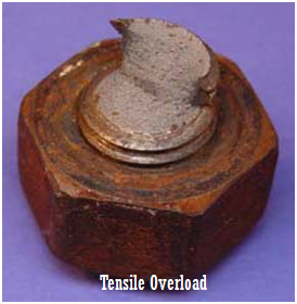 |
| Figure 1: Close-Up overal view of bolt that failed by tensile overload/tensile bending fracture [1] |
Fatigue:
Fluctuating loads over a
relatively long time causes this type of failure and usually leaves clues.
 |
| Figure 2 Results of high-temperature fatigue analysis of a prototype automotive piston show a failure as calculated by fe-safe. One design change to make the piston more fatigue resistant increased the radius of the fillet where the crack initiates Corrosion substantially reduces the fatigue strength of most metals and eventually causes failure at relatively light loads. |
Apparently,
the most common mode of failure in metallic parts is fatigue. Determination of
a maintenance policy after the occurrence of a fatigue failure in service is
based on finding the number of loading cycles that caused the failure [2]. The
compression of gas within a plant is integral to the oil industry, too. It is
thus of the utmost importance that premature failure of these pieces of
equipment be avoided [3]. The rupture of metal parts is a complex phenomenon that
depends on the nature of the material (composition, structure, and morphology),
temperature, the deformation or excitation mode (traction, flexure, fatigue,
etc.), and the rate at which strain is applied [4-5]. An examination of the fracture
surfaces can provide information regarding the origin and cause of the
fracture; these causes may include the apparent heterogeneity, ductility, and,
sometimes, the grain size. When a metal piece breaks, two major questions should
be answered: what are the modes and speed of rupture, and what is the origin of
the damage (metallurgical failure, manufacturing defects, etc.) [4]. Damage tolerant
fatigue design methods for critical rotating components, such as discs and
shafts in gas turbine engines, are well established. These address crack
propagation through the application of fracture mechanics, assuming defects are
present in the material. The prediction methods have limitations; but at lower
temperatures, these are conservative. It is not clear, however, if similar
conservatism is valid at higher temperatures where additional failure modes due
to creep and environment interact with those arising from fatigue [6].
Influenced fatigue:
Corrosion:
The failure is the result of the electrical or biological action of the corrosion, causing a loss of material.
The failure is the result of the electrical or biological action of the corrosion, causing a loss of material.
Wear:
A variety of mechanisms result in loss of material by mechanical removal
A variety of mechanisms result in loss of material by mechanical removal
Reference:
- Jerner,R. C: Fastener Failure, http://www.metallurgist.com/html/FastenerFailures.htm
- Hershko, E., Mandelker, N., Gheorghiu, G., Sheinkopf, H., Cohen, I., and O. Levy, “Assessment of fatigue striation counting accuracy using high resolution scanning electron microscope,” Engineering Failure Analysis, 2008, pp. 20–27.
- Bennekom, A. van, Berndt, F., and Rassool, M.N., “Pump impeller failures—A compendium of case studies,” Engineering Failure Analysis, 2001, pp. 145–156.
- Boutarek, N., Saїdi, D., Acheheb, M.A., Iggui, M., Bouterfaїa, S., “Competition between three damaging mechanisms in the fractured surface of an Inconel 713 superalloy,” Materials Characterization, 2007.
- Wei R.P. and Gangloff, R.P., Fracture Mechanics: Perspectives and Directions, Philadelphia: American Society for Testing and Materials, 1989.
- Hurley, P.J., Whittaker, M.T., Webster, P., and Evans, W.J., “A methodology for predicting creep/fatigue crack growth rates in Ti 6246,” International Journal of Fatigue, 2007, pp. 1702–1710.
No comments:
Post a Comment